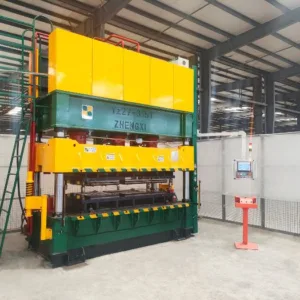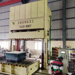

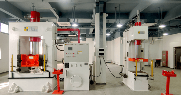
Metal deep drawing hydraulic press is a hydraulic press specially designed and manufactured for aluminum, copper products, stainless steel, and thin iron products industry, especially suitable for sheet metal drawing and stainless steel and sheet pressing.
Features of Deep Drawing Hydraulic Press with Moving Workbench
1. Mainframe:
The frame-type hydraulic machine body is an integral frame structure, composed of steel welded structural parts, with side windows left in the middle of the left and right pillars, using Q355B high-quality steel plate welding structure, carbon dioxide gas shielded welding; after welding, it needs to pass through Annealing treatment eliminates welding deformation and stress, ensuring that the welded parts are durable and not deformed, and the accuracy is maintained.
The lower beam, pillars, and upper beam are pre-tightened by tie rods (hydraulic pre-tightening) to form a combined frame; there is a sliding block in the middle of the fuselage, and the sliding block is guided by a wedge-type four-corner and octagonal guide rail, and the sliding block guide plate is made of A3+CuPb10Sn10 composite material, The guide rail on the pillar adopts a detachable guide rail.
①Upper beam and bottom beam: The upper beam and bottom beam are welded by Q355B steel plate, and the internal stress is eliminated after welding to ensure the stability of the structure and accuracy of the equipment itself. A central cylinder installation hole is machined on the upper beam. A hydraulic cushion cylinder and a hydraulic cushion are installed inside the bottom beam.
② Pillar: The Pillar is welded by Q355B steel plate, and stress relief treatment is carried out after welding. An adjustable sliding block guide is installed on the pillar.
③Tie rod and lock nut: The tie rod and lock nut material is 45# steel. The tie rod matches the female lock thread and is pre-tightened by the ultra-high-pressure pre-tightening device to lock the body.
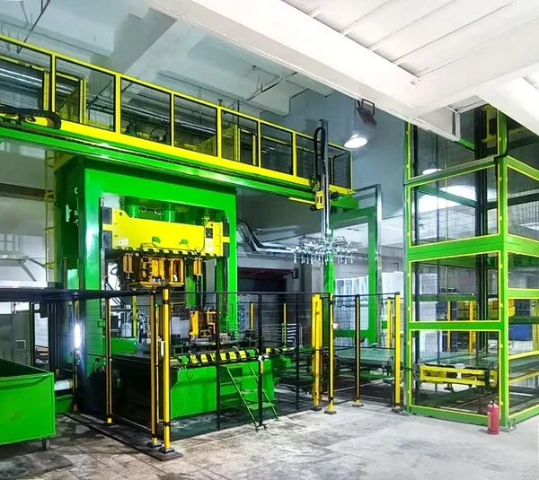
2. Slider:
The slider is a steel plate welded box-shaped structure, and the bottom panel of the slider is a whole piece of steel plate to ensure sufficient rigidity and strength. The slider of the frame-type hydraulic press for automobile body car cover forming frame adopts four-corner and eight-sided guide rails. There are 4 sets of guide blocks on the left and right pillars. The guide plates of the slider move vertically on the guide rails, and the movement guidance accuracy depends on the slider guide rails.
The inclined iron is adjusted to ensure the parallelism with the mobile worktable, convenient adjustment, high adjustment accuracy, good accuracy retention after adjustment, and strong anti-eccentric load ability. One side of the guide rail friction pair is made of alloy material, and the other is made of copper-based alloy material. In addition, the guide rail has been quenched, with a hardness above HRC55, good wear resistance, and long service life. The slide rail surface has a lubricating hole for automatic lubrication to lubricate the moving parts. The fine adjustment of the slider is realized by the control of the proportional flow valve, which is used for fine adjustment and mold clamping during mold trial selection, and can be adjusted within the range of 0.5-2mm/s.
3. Moving workbench:
The frame-type hydraulic press for forming automobile body shell covers is equipped with a forward-moving worktable. The moving worktable is a Q355B steel plate welding structure. After welding, stress relief treatment is carried out. The moving worktable is processed with “T” grooves and ejector holes. The dimensions of the “T” groove and the ejector pin hole are made according to the layout drawing provided by Party A. Leave 400mm in the middle of the “T” groove without milling. Equipped with corresponding ejector rod and dust cover, the heat treatment hardness of ejector rod is above HRC42 degrees.
The repetitive positioning accuracy of the mobile worktable is ±0.05mm, and the driving mode is geared with a speed reducer, and it is a self-propelled structure. With the fitting detection device, the host is not allowed to work when the gap between the lower plane of the moving worktable and the bottom beam is greater than 0.3mm. Provide all mandrel hole covers. There is a cross die slot on the plane of the worktable, the size of which is 14mm wide by 6mm deep.